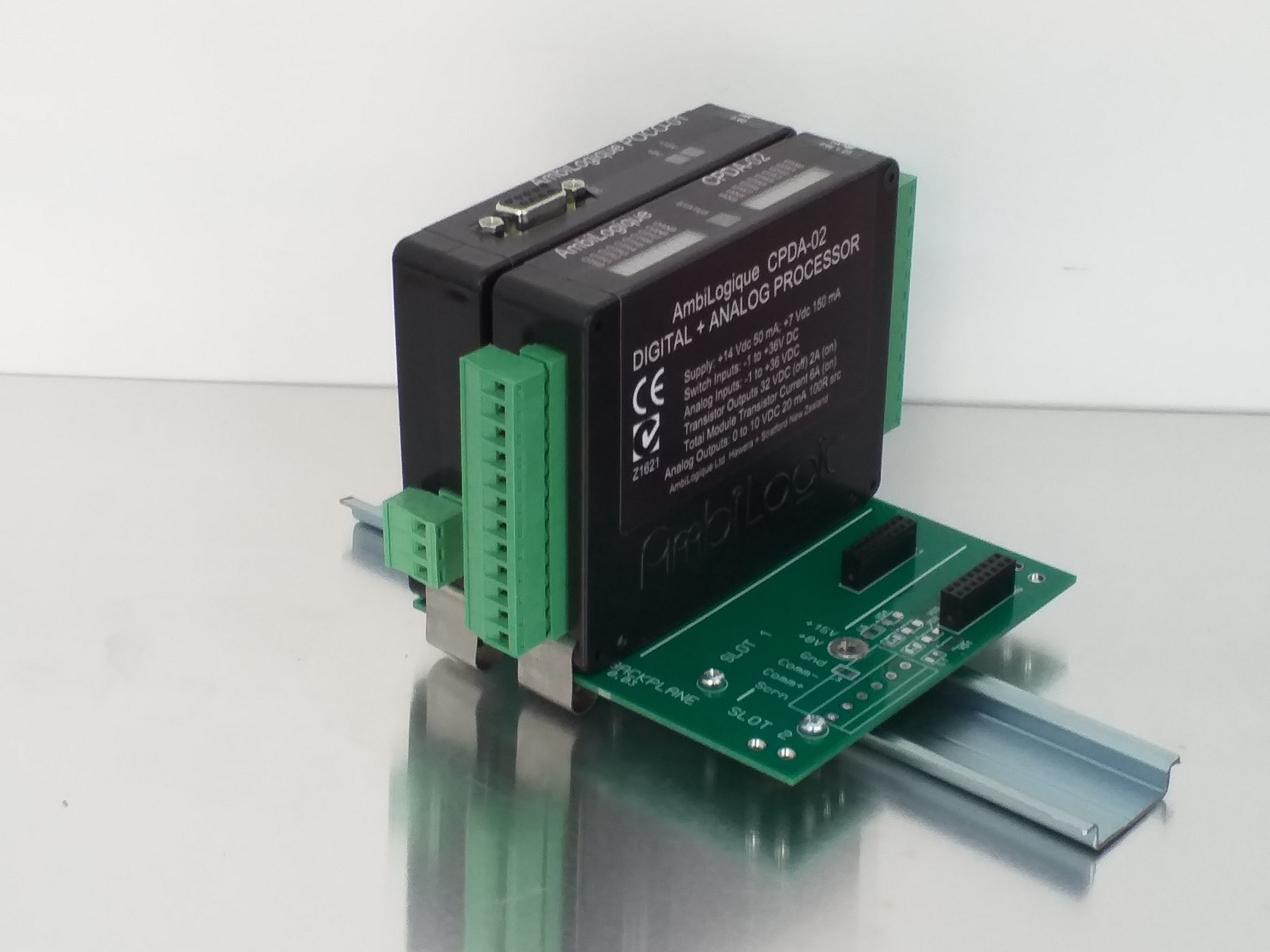
The Backplane is a printed circuit board, fitted with clips which fasten on to a TS35 DIN rail within your control cabinet.
With the connectors at the top, arrange each of the clips so that the tab (see the diagram) is pointing downwards.
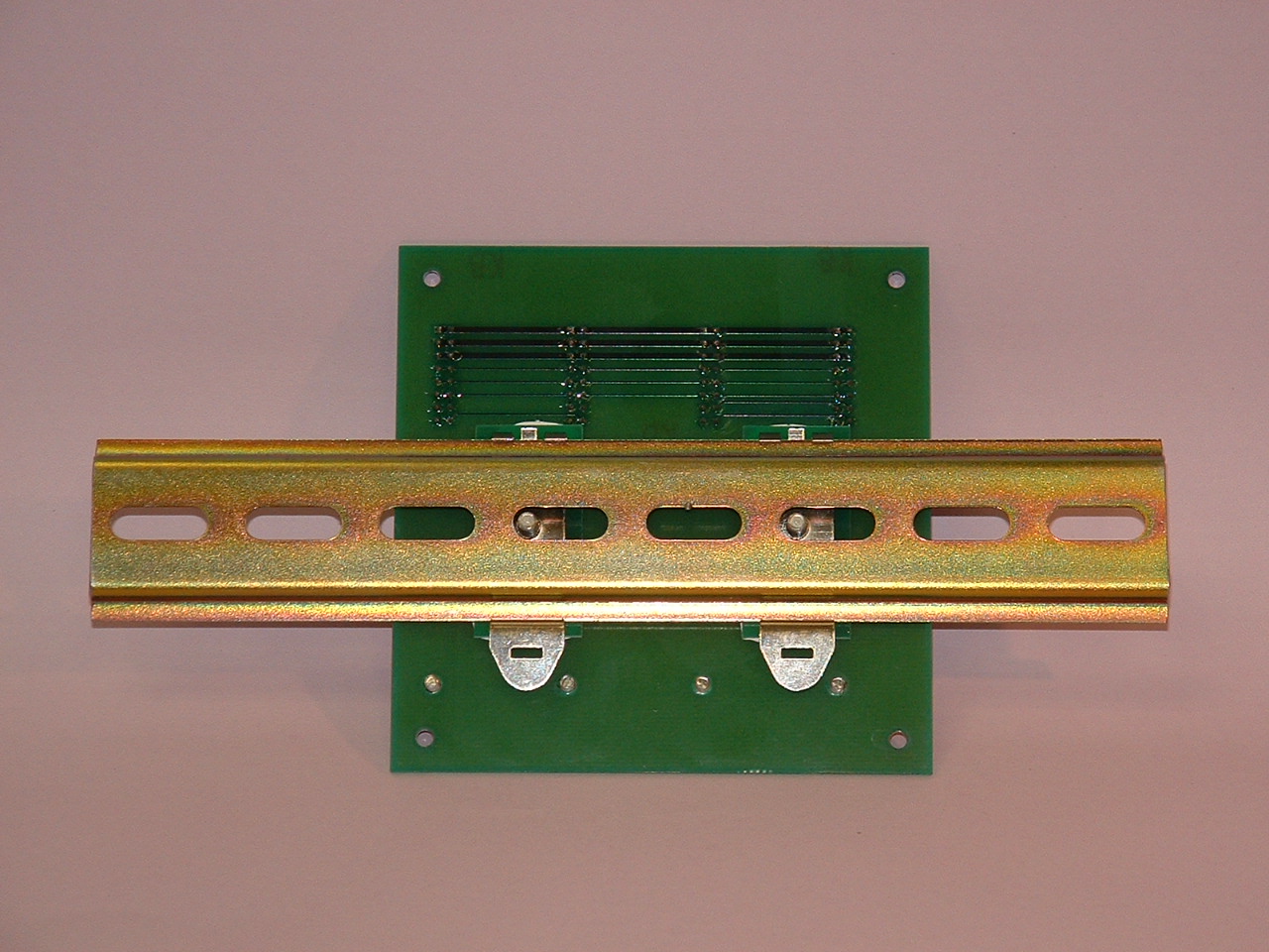
The fixing screws should be slack.
Hook the clips over the top lip of the rail, then swing the backplane
downwards until the clips 'click' over the bottom of the rail.
Once all the clips are latched in this way, tighten the screws so
that the clips are pulled up against the back of the backplane.
The screws do not have to be excessively tight - just closed up
is quite enough.
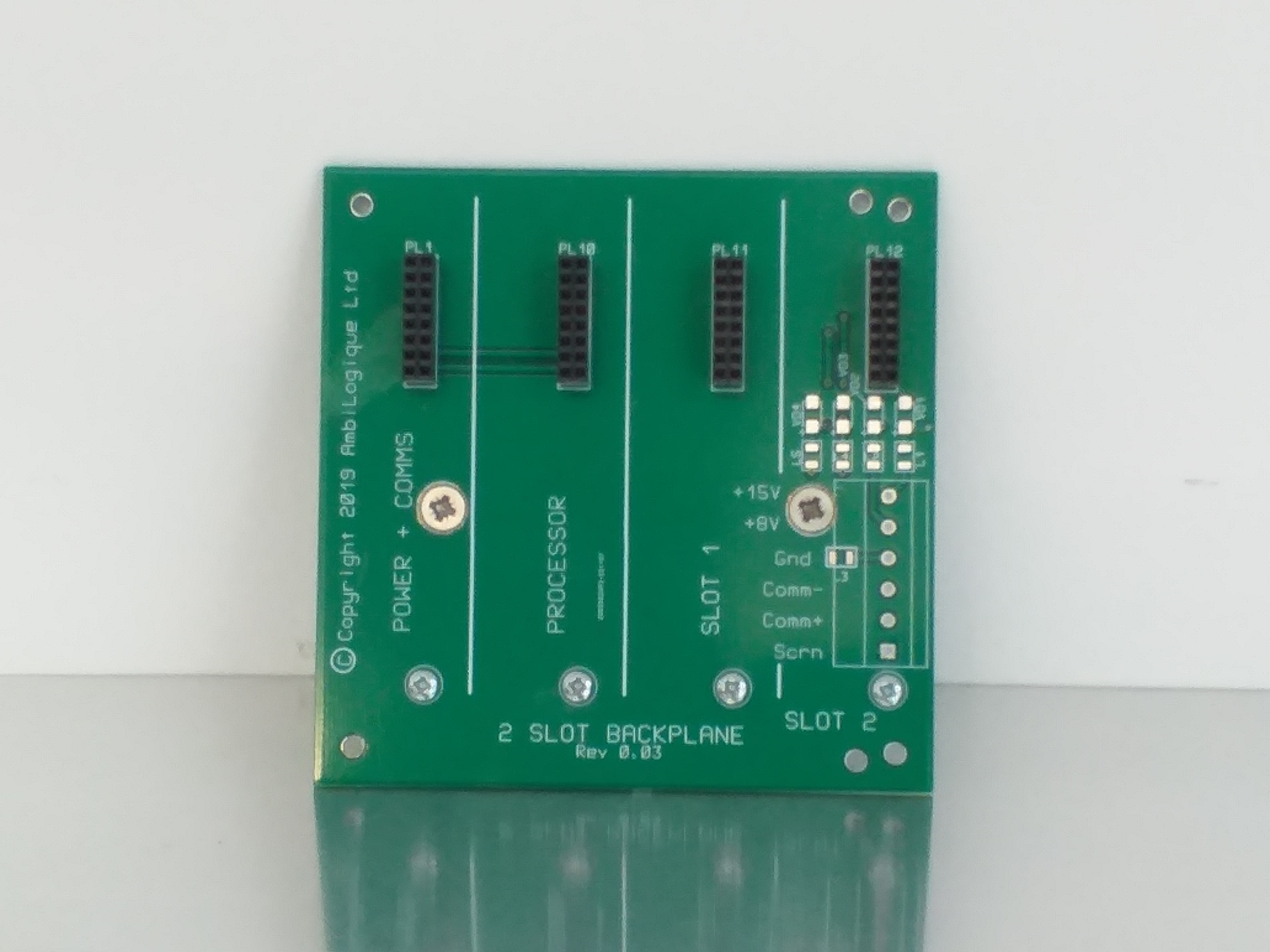
Looking at the backplane itself, you will see that the slots (the positions into which the modules plug) are labelled.
Starting from the left, the first slot is for the Power Module.
If you have a starter kit or an evaluation kit, a Power Module will
be included.
Pull the springs out as far as they will go, then locate the
module on the screw head at the bottom of the backplane slot.
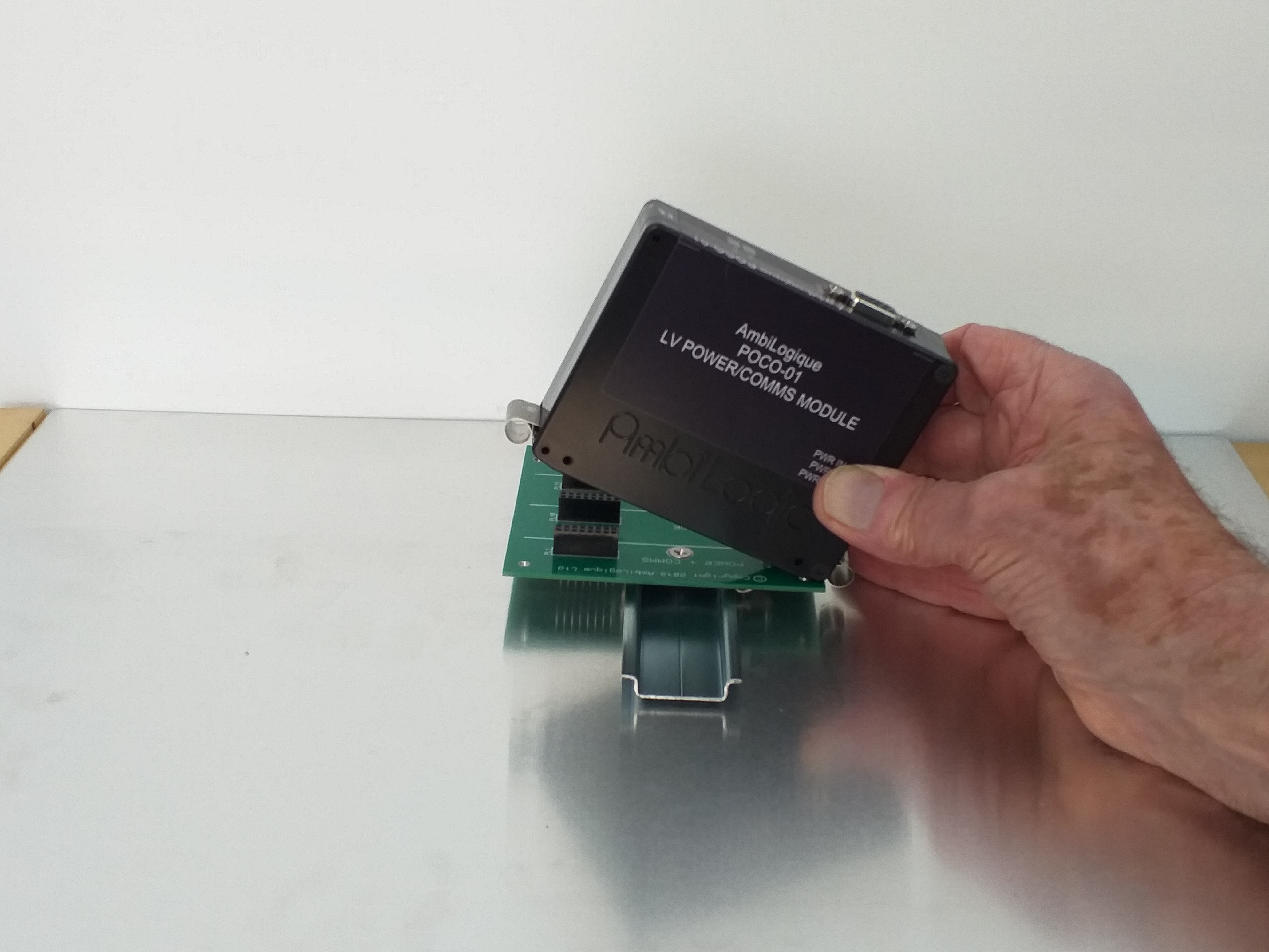
This will line up the socket on the backplane with the plug in the
module.
Now plug the module in, ensuring that the plug and socket line up
and connect correctly, then clip the retaining springs round the
top and bottom edges of the backplane.
The second slot is for the Processor Module. This is
Slot 0.
You will need to know this when you start to build diagrams.
Your processor contains the "engine" which drives AmbiLogique,
and which will execute your diagram many times each second once you
have programmed it.
The Processor Module also provides a starter set of inputs and outputs,
so you can build a complete working system with just 3 elements: the
Backplane, the Power Module and the Processor Module.
The Processor Module is installed in the same way as the Power Module.
Expansion modules provide different mixes of specialized input and output, and in some cases provide complete control facilities in themselves, for example, motor controllers.
These expansion modules can be plugged into the slots numbered
1 and upwards, in any order.
You need to know the slot number of every facility in the
control box you are building, because this slot number forms
part of the complete address of any input or output terminal
on the diagram you will build as part of the programming process.
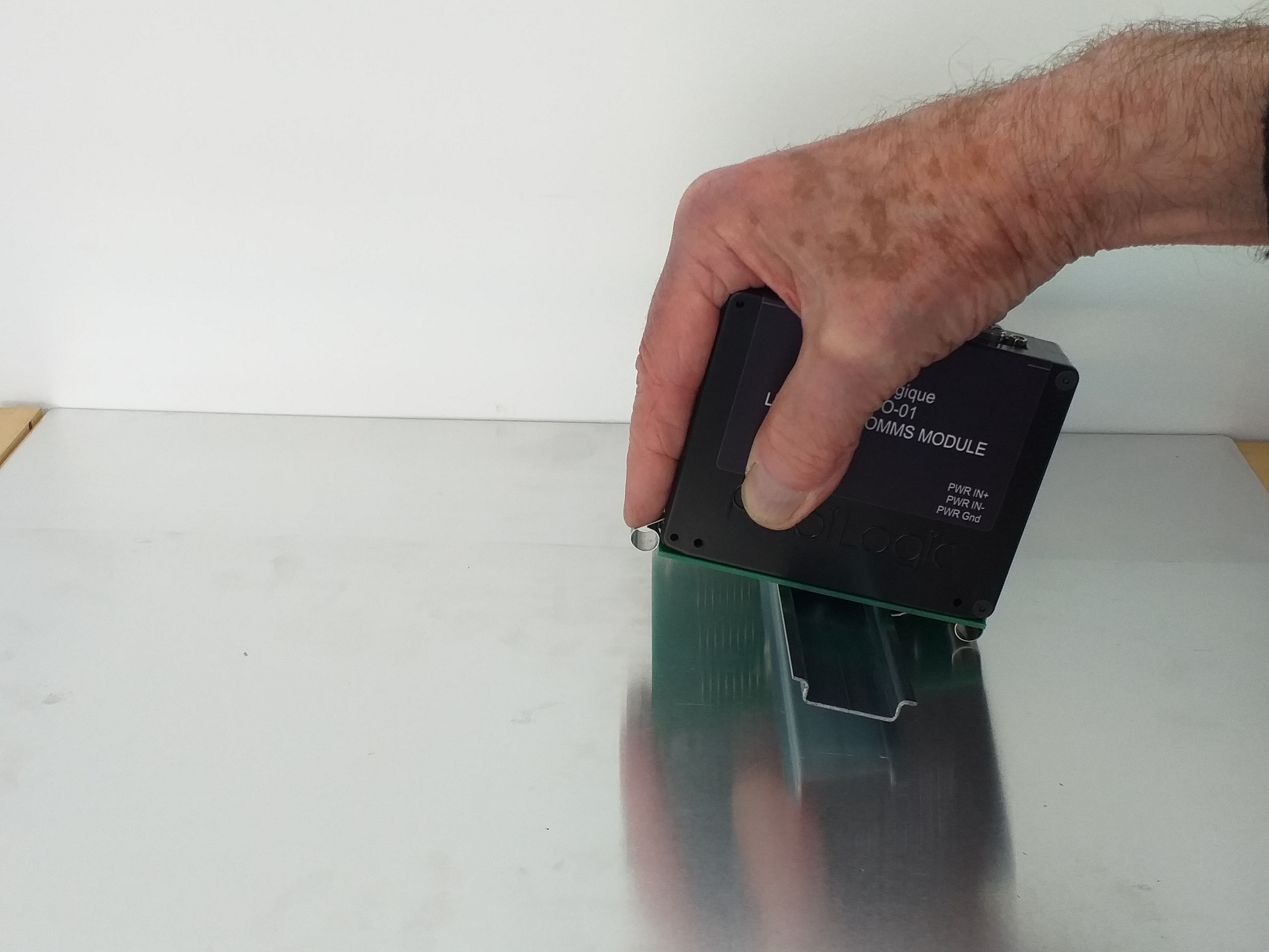
Electrical connections are made to the screw terminals along the
top and bottom edges of the modules.
You will need to refer to the data sheet for the module for
guidance on how to connect the various input and output connections
to your external circuits.
For your convenience, these screw terminals are detachable
from the modules.
In a production-line environment, you can purchase loose terminal
blocks so that you can pre-wire panels, fit the AmbiLogique modules
at the last minute, and simply plug in the connections.
Data sheets for the modules can be found on the AmbiLogique website.
If you have an evaluation kit, you have only to plug the test panel into the Power/Comms and Processor modules, and you are ready to run.