Look at the Power/Comms Module data sheet. This will give details of the power supply required for the PLC system. For example the POCO-01 requires a power supply of 12 or 24 Vdc at 0.2A.
Wire the power supply to the Power/Comms module with the correct polarity.
Note:
A ground or earth connection is provided on the Power/Comms Module.
This must be connected to a suitable
EMC earth via a short wire link in order to ensure compliance with
international EMC standards.
Whilst in many cases leaving this earth unconnected or using a wire
of more than 60 mm in length will not cause a problem, correct
earthing will ensure compliance.
First, find a free RS-232 plug on your computer, and work out which
COM number it is.
The best way is to click the "Start" button on the computer
desktop, select "Control Panel" then "Device Manager."
On some Windows installations, Device Manager is a sub-item of
"Control Panel \ System."
On Windows 10 and 11 computers, right-clicking the Windows icon in the system tray will throw up a dialog box with Device Manager as one of the options.
Most modern portable computers do not have a serial RS-232 communications
adaptor built in.
You can purchase a USB-to-Serial adaptor which will provide this
facility at minimal cost from any competent computer shop.
It is a good idea to get a 9-pin 'D' extension cable at the same time.
The cable needs to end in a plug (with pins) at the PLC end.
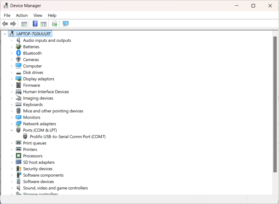
In Device Manager, expand the 'Ports (COM & LPT)' item:
In the example above, the USB-to-Serial adaptor registered as COM7. That '7' is the number you need.
Connect the RS-232 cable to the socket on the top of the Power/Comms Module.
The cable in use must be a straight pin-to-pin connection, not a crossover
cable for connecting two computers together.
Some games consoles use straight pin-to-pin 9-way cables, and such
cables normally work very well.
Select "Project->Connect-to-target" from the menu, and a COM port selection dialog will appear.
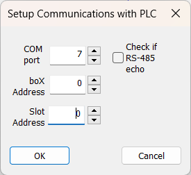
Choose the correct number for the port you are using, and click OK.
AmbiLogique will now attempt a dialog with the controller in order to
find out its type identifier.
If successful, it will tell you what controller it has found at the
end of the cable, otherwise it will report that the connection has
failed.
When a successful connection has been made, the COM number is
remembered for future connections.
NEW IN REVISION 3.32 AND ABOVE - EXTENDED CONNECT DIALOG
In addition to the COM port selection, there are several new controls on the dialog:
Once the connection has been established, a tick (check mark) appears beside the "Connect-to-target" menu item, and the items below become full density, indicating that they are available.
When communication has been established with the PLC, it is possible to
view some of its internal parameters.
This menu item brings up a dialog which displays as follows:-
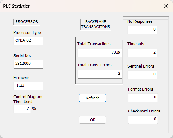
Pressing the "Refresh" button will update the Time Used and Backplane statistics.
Note that the Serial Number will only display for CPDA-01 from firmware 3.61 onwards. All CPDA-02 processors display their Serial Number.
The Control Diagram Time Used depends on the size of the control diagram and the mix of function blocks used in the diagram. The scan time available is 62.5 milliseconds on a CPDA-01 or -02, and the Time Used is expressed as a percentage of this time.
Select "Project->Upload-to-target" from the menu.
A warning dialog appears, telling you that you are about to perform
an operation which requires that the processor be
stopped.
You have the opportunity to Cancel, if this is not what you intended.
If you want to load your diagram, select OK.
The target processor is stopped, and its
Status LED
starts to flash rapidly, indicating that it is no longer running
its diagram.
First the constants from your diagram are loaded, then the function
blocks.
The constants are then verified, followed by verification of the
function blocks.
For each operation, a progress bar is shown.
Note that if you have only one or two constants to load, you may not
see the progress bar for this operation because it is so quick.
When the diagram has been successfully loaded and verified,
you will see a dialog box advising you that the Upload process
verified OK.
When you press the OK button, the processor is restarted, and it
then runs the new diagram until you switch it off, or upload a
new diagram.
Select "Project->Verify-target" from the menu.
The verification process is exactly the same as takes place after a
new diagram has been uploaded.
You need to be sure that you are looking at one of the sheets of the
diagram which is installed in the controller.
Verifying does not interfere with the operation of the controller,
and it is not necessary to take the controlled process off line.
The verification stops on the first difference between the diagram
you are looking at (remember that all the sheets are checked,
not just the one in view) and the diagram in the controller.
If the diagrams are the same, you will see a dialog which says
"Verified OK."
The controller will run its diagram automatically as soon as it has
been loaded and verified.
It will also start in Run mode when it is first switched on.
Only a special computer command will stop it.
When the PLC is running a diagram normally, the Status LED on the top
panel of the controller flashes once per second.
The duration of the flash is proportional to the time taken to
process the diagram each scan - so you can tell if there is
processing time available to extend the diagram.
Note that the AmbiLogique controller is processing its diagram much
faster than this, for example the CPDA-02 processes a full diagram
16 times per second.
When the processor is stopped, the Status LED flashes rapidly - 8 times per second.
If the Status LED is permanently on, there is a failure in the controller.
If the Status LED is permanently off, either there is no power being supplied to the controller, or the controller has failed.
Select "Project->Monitor-target" from the menu.
This does not interfere with the operation of the controller.
The internal signals in the controller are continuously read out, and
are displayed wherever there is a visible signal name on the diagram.
If you have a wire on the diagram whose signal is not displayed,
and you want to see it, right-click on the wire segment, select
"Properties," and tick the "Show signal name"
check box.
You will then need to stop and re-start the Monitor process
(so that the Monitor signal list gets updated), then the signal
value will be displayed below the signal name.
You will need to cancel the Monitor mode if you want to do any
other communication process with the target controller.
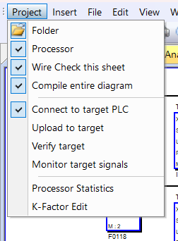
Pull down the "Project" menu item, and you will see that
there is a check mark against the "Monitor-target" item,
also that all the other communications options are grayed out.
Clicking on "Monitor-target" will cancel Monitor mode, and
the other options become available again.
K-Factors are an extremely valuable addition to the CPDA-02 toolset. These factors are used to set semi-permanent constants in the control diagram, but which can be edited and tuned without stopping the process being controlled.
K-Factors are defined in a script file named “KF****.txt” where the stars represent any textual characters. The file name can be any that conforms to the file name specifications of the operating system, so long as it starts with the upper case “KF” and carries the “.txt” extension.
Each K-Factor is connected into the control diagram via a TERMIN function block with:-
Just as with any other instance of a TERMIN, the signal can be masked to filter specific bits in or out of the signal.
Each K-Factor is assigned to one, and only one line of the file.
The fields of each line of a K-Factor file are separated by tabs. They are as follows:
The serial number is one less than the line number, i.e. the first entry is 0, the second 1, etc.
The factor name is a string which has a meaning relevant to
the application.
Note that a factor name cannot include spaces, so multi-word names
are best linked_up_with_underscores in lieu of spaces.
The lowest and highest recommended values are there
as a user guide, and do not have any function, specifically
they do not constrain the user input.
Because of this, users need to be careful when editing K-Factors.
The start value is useful for commissioning new systems, as the K-Factor Editor allows for all of the Start values to be loaded into the edit boxes at once, which is much more efficient than typing them in individually.
A typical K-Factor file looks like this:
0 CTG_Closed_% 40 100 32.7
1 CTG_Gnd_Idle_% 25 40 41.4
2 CTG_Flt_Idle_% 15 70 67.7
3 CTG_Full_Pwr_% 0 100 84
4 T.Motor_P_Factor 0 200 120
and so on. Please don't put a blank line at the end of the file.
The great thing about K-Factors is that they can be changed whilst a live process is being controlled, without disrupting the process.
With the computer connected to the PLC, select the 'K-Factor Edit' item from the 'Project' menu.
A file selector dialog pops up, looking for a K-Factor file with the appropriate file name and type.
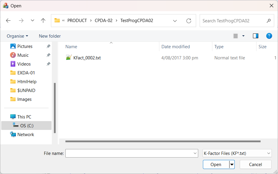
The system looks in the current project folder first, but you can choose to locate the K-Factor file anywhere.
Once you have selected the folder and opened it, the K-Factor Editor opens.
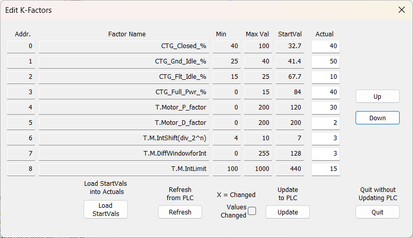
You will recognise most of the content of the page as a copy of the K-Factor file contents.
The white boxes on the right contain the actual values retrieved
from the PLC.
These can be freely edited: if you change any of them, the
'Values Changed' check box will show an 'X'.
If you have more than 9 K-Factors in your project, the hidden ones can be revealed using the 'Up' and 'Down' buttons.
With a new PLC, the K-Factors will be set to all 1's, so you
may need to put the Start Values into the edit boxes.
This is the purpose of the 'Load StartVals' button.
If you make a mistake, you can always refresh the edit boxes from the PLC using the 'Refresh from PLC' button.
When you have finished editing, you have two options: load your new values into the PLC using the 'Update to PLC' button, or abandoning the exercise with the 'Quit' button.
Technical Note:
During the update, the PLC makes a temporary copy of the
old K-Factors and continues to run with these until the
new block is completely uploaded.
Then it waits till the end of the current diagram scan,
and only then switches to the new values.
This means that the only effect on the controlled process
is a possible jump due to the new K-Factor values.
It also means that the PLC never runs with a partially
updated set of K-Factors.
After updating, you can use the 'Refresh from PLC' button to confirm that the new values are indeed loaded into the PLC.
Note that even after sending your revised values to the PLC, you will need to close the dialog by means of the 'Quit' button.
Hint:
When your project is fully developed, it is worth editing the
final K-Factors back into the script file as start values.
Then they can be quickly restored to the PLC if required.