Each AmbiLogique project
occupies a single folder in the Windows file system.
It is not possible for more than one project to occupy a single
folder, nor is it possible for a project to occupy more than
one folder
It's one project, one folder.
A new project folder can be created in one of two ways:-
From within AmbiL_PLC:
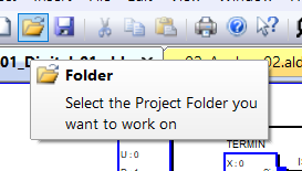
Use the Project->Folder menu sequence. This will open a File Open dialog:
Using the tools within this dialog, navigate to where you want
the new project folder to be.
Use the New Folder button to create a new folder,
then rename it with the name of your project.
Using Windows Explorer: (not Internet Explorer!):
Visually navigate to where you want your new folder to be.
Use menu sequence File->New->Folder to create a new folder, then rename
it with the name of your project.
The following files can be found in a completed project folder:-
This file, called "project.alp" is created and maintained
automatically by AmbiL_PLC.
It is used to maintain control of the project progress, and contains
details of which sheets have been wire-checked, whether the project
has been compiled, and if there are any errors.
It also contains details of the serial communications settings.
These are the diagrams which you, the programmer, create and maintain.
Each sheet forms part of the complete diagram which the AmbiLogique
target system
will execute in service.
These diagram sheets are the only files which you need to create
for yourself.
All of the sheets in the folder are treated as one diagram, as if they were joined together in one large (or huge!) diagram.
A little later you will learn how the connections between sheets are made.
This file, called "project.alb," is generated
automatically by AmbiL_PLC when you compile your project.
You do not have to worry about creating or maintaining it.
AmbiL_PLC uses this file to work out what information it needs
to upload a control diagram into the target controller.
There are two files, called "fblock.lst"
and "wires.lst"
They are generated automatically by AmbiL_PLC when you compile
your project.
If there are errors in your project, they will be marked up in
the listing file.
This file is a plain text file so that you can examine it with
an ordinary text editor such as Notepad or Wordpad.
You may need to open this file in order to find errors in
your diagrams.
Errors are flagged in the listings with 4 asterisks "****"
so that you can search for them quickly.
See Examples.
Most errors within a diagram sheet are picked up on the
Wire Check.
These are flagged on the diagram by showing the wire segments
which contain errors as dotted lines.
You should only need to consult the listing files to resolve errors
which arise in the connections between sheets.
There are four kinds of active component which you can place on
diagrams:
Function Blocks,
Wires,
Cross References
and Constants.
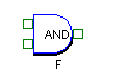
Function Blocks are the active components of AmbiLogique diagrams.
They provide a range of arithmetic (add, subtract etc.),
logic (AND, OR etc.) and other functions.
These include timers, data selectors, flipflops, etc..
A special class of function blocks provides connections to the input
and output terminals of your system.
Each of these function blocks corresponds to a function within
the AmbiLogique target system.
You can use any function block (including timers) as many times
as you like on any diagram.
Some PLCs limit the number of timers you can use - with AmbiLogique
there is a limit only on the number of function blocks in total.
 A typical Function Block
This is the shadowed outline which lies inside the pins.
In some cases it is a rectangle, whilst in others, such as gates,
it is a more complex shape.
It contains the pin names or value boxes.
These are the small boxes along the left and right edges of the
function block body.
The input pins are on the left side of the function block,
and the output pin is on the right side.
Notice that there is only one output pin per function block.
This is a unique feature of AmbiLogique diagrams, and it makes
them much easier to understand.
Strictly speaking, there are four types of pin: one of them
(no-pin) you obviously never see.
The other three are:
The Analogue pins are shown as solid blue squares.
![]() These just pass the signal into or out of the function block without
modification.
These just pass the signal into or out of the function block without
modification.
Mostly you will connect analogue signals (those which can have lots
of different values) to these pins, but you are not forced to.
The two types of Digital pin convert the signals
passing through them to binary (true/false) signals.
If you connect an analogue signal, it is just tested to see if
it is zero or not.
If it's zero, it is considered False; otherwise it is True.
The Digital Normal pin (green hollow square)
![]() passes the binary form of the signal straight through.
passes the binary form of the signal straight through.
The Digital Inverting pin (red square with a cross
in it)
![]() swaps the True/False state over as it passes through: if the signal
comes into the pin True, it leaves it False; and vice versa.
swaps the True/False state over as it passes through: if the signal
comes into the pin True, it leaves it False; and vice versa.
The great thing about these digital pins is that you can
exchange one for the other at will.
If you see a digital pin on the diagram and you want to exchange it,
just right-click on it and you will get a pop-up menu which includes
the "Invert Pin" option.
Select this option and you will invert the sense of the pin.
This mechanism greatly reduces the number of function blocks
you need to learn.
Many function blocks allow you to change the number of input pins.
For example, the AND, OR and XOR gates allow you to have between
2 and 15 inputs.
Right-clicking on one of the input pins of one of these function
blocks brings up a menu which has the "Add Pin"
and "Delete Pin" options.
If these are grayed out, we're sorry, you can't change the number
of pins on that block.
If these menu items are active however, a pin will be added or
removed at the bottom of the input array.
It doesn't matter which pin you right-click, the add or delete
always occurs at the bottom of the input array.
This mechanism also reduces the number of function blocks you
need to learn.
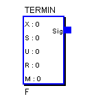
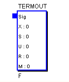
Input and Output Terminals are connected to the diagram by means of special function blocks, called TERMIN (for input terminals) and TERMOUT (for output terminals).
The TERMIN block has only an output pin.
This is where the signal from your chosen physical terminal
will enter your diagram.
The TERMOUT block has only a single input pin (and it is the only
function block without an output pin!)
The input pin is how your diagram influences the outside world
by sending a signal to the physical output terminal.
Both of these special function blocks have value boxes which allow you to select the exact terminal which will be attached to the function block.
![]()
Value boxes appear within the body of some function blocks.
Input and output terminals are examples of function blocks with
value boxes.
In these cases the value boxes determine the address of the physical
terminal to which the input or output block is attached.
To change the values within the function blocks, right-click
on the function block body and choose 'Properties' from the menu
which appears.
A dialog box will appear which looks like a normal function block
dialog, but with some extra fields in which the value boxes can be
edited.
For example, opening a TERMIN function block in this way allows
you to edit the boX, Slot, sUbslot, Register and Mask values
for the terminal you want to attach.
The data sheet for the processor or expansion module will tell
you what the Register and Mask values are for the terminal:
the Slot and Subslot values are determined by how you plug your
system together.
Wires are special components which connects pins on your
diagram together.
Wires are inserted using the
Wiring Tool.
This can be selected by pressing the Wiring Button on the toolbar or
by selecting 'Wires' from the Insert menu on the main diagram menu
bar.
Wires are composed of one or more wire segments:
a wire segment is a straight run of wire from a pin, junction,
bend or cross-reference to another pin, junction, bend or
cross-reference.
Every wire has a name which represents the signal
that it carries.
You can have wires with the same name in different parts of the
diagram, but please remember that AmbiL_PLC will connect wires
with the same signal name together when it compiles the diagram.
Wire names are assigned automatically by AmbiL_PLC unless you
change the name manually.
By default, AmbiL_PLC will name a wire with the name of the
function block which drives it.
This means that you must manually assign a name to an incoming
cross-reference, and you must manually assign a value to a constant.
Cross-references and constants are explained a little later.
Don't confuse Wires and Decorative Lines.
Wires connect pins together - lines do not connect anything.
Wires appear in the diagram coloured black, lines are
coloured blue (unless you change the line colour - please don't
change them to black!).
You can't change the colour of wires.
Often we need to connect points together which are inconveniently
separate.
They might be far apart on one sheet, or they might be on separate
sheets.
These awkward connections are made through cross-references.
An outgoing cross-reference is a wire with an open
destination end - it does not connect to a pin at the destination
end.
AmbiL_PLC will automatically display the signal name just above the
open end of the wire.
![]()
An incoming cross-reference is a wire with an open
source end - it does not connect to a pin at the source end.
Again, AmbiL_PLC will automatically display the signal name just
above the open end of the wire.
![]()
If you ensure that the signal name on an incoming cross-reference is the same as one of your outgoing cross-references, AmbiL_PLC will connect them together.
Cross-references follow the same source-destination rule as wires.
There is only one outgoing cross-reference, which can connect to
as many incoming cross-references as you want.
Signal names must not be numeric and should not be numbers with
an 'e' or an 'E' in the middle of them.
You'll see why in a moment.
![]()
A constant is like an incoming cross-reference (a wire with its
source end unconnected), but its signal name is something which
AmbiL_PLC can interpret as a pure numeric value.
Some examples are:-
0 2 3.142 -27.3 1.475E-6 2.45E9
The last two examples are floating-point values in exponential
format.
The 'E' represents "10 to the power of" and is used
to represent very large or very small values.
There are two kinds of passive component you can place on a diagram to make it look better or easier to understand: Text and Decorative Lines
Text or notes can be added anywhere on the diagram except inside
Function Blocks.
These notes do not affect the functioning of the diagram.
It is a good idea to avoid placing text above wires where it might
be mistaken for a signal name.
You can change the size of text, either when you enter it on the
diagram, or later.
Decorative lines can be added to a diagram, running horizontally
or vertically.
They do not affect the functioning of the diagram.
These lines can be used to divide the diagram into different areas, to outline text or special functions, to create a drawing frame, or any other purpose you desire.
Lines are normally blue, 2 dots wide, but you can subsequently
change the colour or width of lines.
This is done by right-clicking on the line and selecting the
appropriate option from the pop-up menu.
This is the first operation which must be performed when you work on a project.
If the project already exists:
Pull down the "Project" menu item and select "Folder".
AmbiL_PLC will attempt to open the project control file "project.alp" in the currently selected folder.
If you want to change the project, you can use the navigation
buttons in the File Open dialog to locate the folder.
When located, choose Open, and the folder will be selected and
the project control file opened.
If you have already carried out some operations on the project
(such as choosing the target Processor), the status of
these operations will be retrieved from the project control file.
If there are already diagram sheets in the project, these will all
be opened with a series of tabs along the top of the workspace.
If there are too many sheets for the available tabs, the extra
tabs are available via a drop-down icon at top right of the workspace.
If you are creating a new project:
A new project folder can be created in one of two ways:-
Pull down the "Project" menu item and choose "Folder"; alternatively use the Folder icon on the toolbar.
Use the Open File dialog to navigate to the place where you want
the new folder to be.
Use the "New Folder" button to create the folder,
then rename "New Folder" to the project name you want.
When you have typed in the new name, press the <Enter>
(or Return) key twice.
The first press confirms the folder name, the second navigates
into the new folder.
AmbiL_PLC is now trying to open a file called "project.alp"
which records information about the progress of the project.
It does not exist in a new folder, but don't worry. Press
the Open button, and AmbiL_PLC will ask you if you want to create
the file: answer Yes.
You can now start working with your first diagram sheet,
which you can call (if necessary using File->Save As)
"Sheet_01.ald"
When choosing file names for diagram sheets, please remember that
the last 2 characters of the file name MUST form a 2-digit number
which is unique to that sheet.
This is because this 2-digit number is taken to be the unique
sheet number and is incorporated into the reference numbers of the
function blocks on that sheet.
If you have more than one sheet with the same reference number,
your control diagram will have unexpected cross-connections in it.
AmbiL_PLC will automatically generate file names with a unique
2-digit number at the end.
Windows Explorer allows you to navigate your disk storage in
a visual manner.
When you have located the place where you want your AmbiLogique
project, use the menu sequence File->New->Folder
to create the new folder.
Once created, the new folder can be renamed to the project name
you want.
When you start the AmbiL_PLC software, you use the
Project->Folder menu sequence to find the folder you created.
AmbiL_PLC will now try to open a file called "project.alp"
which records information about the progress of the project.
It does not exist in a new folder, but don't worry.
Press the Open button, and AmbiL_PLC will ask you if you want to
create the file: answer Yes.
You can now start working with your first diagram sheet, which you can call (if necessary using File->Save As) "Sheet_01.ald"
Note:
AmbiL_PLC will automatically name diagram sheets
"Sheet_01.ald", "Sheet_02.ald" etc..
The number at the end of the file name, however many digits,
is called the "suffix."
AmbiL_PLC manages suffixes in the following way: when a new file is
created, the first available suffix starting from "01" is
used and added to "Sheet_" to form the name of the new
file.
AmbiLogique diagram sheets can have any name you want
with the restriction that each sheet name must end with a
unique number in that project folder.
Use the menu sequence Project->Processor. This will bring up a list of the available processor library files on your system.
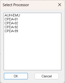
Most users have just the starter kit with the CPDA-02 as the
only option (you may find more than one revision of the library
on your system - select the most recent).
You must choose a processor before you can go further with your
project.
If you have not selected a processor, you have no library of
function blocks with which to build your diagrams.
Once you have chosen your processor, the Function Block button and the Insert->Function Block menu item become active, and are no longer "grayed out."
We will now work with Example01, the corridor lighting project.
The electricians among you will declare that you don't need a PLC
to do this trivial job - but we are just using it to illustrate
the basic principles of carrying out an AmbiLogique project.
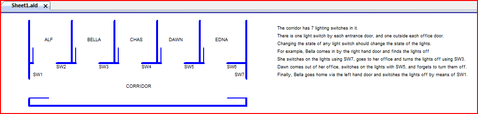
In the corridor lighting example, one of the first things
we can do is to look at the output required.
We are going to connect the output of the CPDA-01 to a relay which
controls the lights.
We decide to use OTR0, the first available digital (on-off) output.
Use the Function Block button
![]() on the toolbar.
on the toolbar.
The Function Block Library dialog pops up, with a tree in the
top left window.
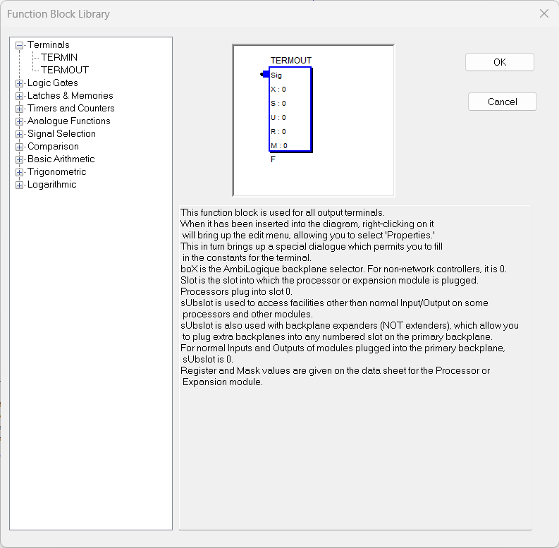
Click on the '+' expansion box to the left of 'Terminals' -
the tree expands at that point to show TERMIN and TERMOUT.
Click on TERMOUT and you will see an image of the function block
appear in the top right window, with a description below.
You can browse through the available function blocks in this way
to gain an idea of what is available.
A unique feature of TERMOUT is that it has no output pin.
This function block routes the incoming signal to the outside
world, so the signal flow in the diagram ends here.
With TERMOUT selected, click on OK.
The Function Block library dialog now disappears, and the cursor has changed to the Function Block cursor.
![]()
The top left pin on the cursor is the "hot spot" which
determines where the top left pin of TERMOUT will land on the
diagram.
Choose somewhere on the right hand side of the diagram sheet
(normal signal flow is from left to right), and left-click.
A TERMOUT block has now been added to our diagram.
If you are not happy with its position, you can place the cursor over it, hold the left button down, notice that a red box appears around the function block and, holding the left button down, drag it to a new place.
A trail of function boxes appears on the diagram but don't worry.
When you have dragged it to the new position,
release the left button.
Left-clicking in a blank area of the diagram is a quick way of
forcing a redraw: do this now, and you will see your diagram
cleaned up with just the TERMOUT in its new position.
Alternatively, right-clicking in a blank area of the diagram pops
up a menu which gives you some useful options for your diagram sheet,
including "Redraw."
These techniques can be used to move any item on the diagram. In addition, multiple items can be selected by:
When positioning items on the diagram, you will observe that
AmbiL_PLC has an invisible grid that it works to - it's about
2.5 mm on normal screens and printers, and every object that you
place on the diagram is snapped to the nearest grid point.
This is another way in which AmbiLogique works silently to make life
easier for you.
We have now added an output terminal to our diagram, but we need
to connect it to the physical terminals we are going to use.
We have decided to use OTR0, and we look at the CPDA-02 data sheet
to find the settings for this terminal facility.
We read that OTR0 is Subslot 0 Register 4 Mask 1.
AmbiLogique has a global addressing system which uses 5
domains to access an individual input or output facility:-
boX, Slot, sUbslot, Register, Mask.
X - the boX address is the address of an AmbiLogique backplane module in an interconnected network. The Starter and Evaluation kits based on the CPDA-02 do not have upstream network facilities, so the boX address is always 0.
S - the Slot number is the slot on the backplane into which the input/output module is plugged. The facility we are going to use is within the processor module which always plugs into slot 0, so the Slot number is 0.
U - Subslot provides different domains within an
AmbiLogique module for advanced control purposes.
For example, the CPDA-01 has subslots for standard input/output,
programming, monitoring signals, external computer control and
K-Factors.
The subslot for our transistor output is given in the CPDA-02
data sheet as 0.
R - Register. This is the actual signal
generated or used by the module which carries the input or
output facility.
A register might be unique to a signal (as in the case of the
analog inputs and outputs on the CPDA-02) or might be shared
among several facilities (like the digital inputs and outputs
on the CPDA-02).
The Register for a given input or output is specified in the
module data sheet.
The Register we are using in this example is 4 - which controls
the transistor outputs of the CPDA-02.
M - Mask is used to pick out individual signals from
a register which carries more than one.
In our example, a Mask value of 1 is used. This
picks up only the least significant bit of the register.
Many times we want to pick up the entire register, and this might
require the use of complicated masks. To make life easy
for you, AmbiLogique will use the entire register if you specify a
Mask value of 0.
The Mask value for a given input or output is specified in the
module data sheet.
Right-click inside the function block body of TERMOUT and choose 'Properties' from the pop-up menu. The Terminal Properties dialog appears.
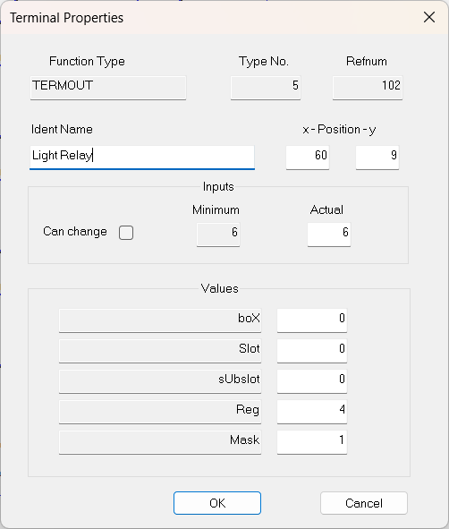
You can now change the name of the function block to "Light Relay", the Reg value to 4 and the Mask value to 1. You will also note that you can move the block by specifying its X and Y co-ordinates, which is useful for lining up blocks to make the diagram look tidy.
Two minor points:
Click on OK and the diagram will show the changes you have made. Any signal you connect to the input pin of TERMOUT will now determine the state of the light relay.
Adding input terminals is similar to the process above, using TERMIN. These boxes need to be on the left hand side of your diagram. You will need 7 input terminals, one for each switch.
There is a quick way of duplicating items using the clipboard.
Once the first TERMIN has been added to the drawing, left-click on it
to select it (indicated by a red border) then either press Ctrl+C
or use the Copy Button
![]() on the toolbar. To add copies to the diagram, either press Ctrl+V or
use the Paste Button
on the toolbar. To add copies to the diagram, either press Ctrl+V or
use the Paste Button
![]() on the toolbar.
on the toolbar.
New copies are added 2 grids to the right and 2 grids below the
original, and are pre-selected so that you can move them.
Any previously selected items on the sheet are automatically
de-selected, even though their outlines sometimes remain red.
It is best to move each copy to its final position as soon as it
has been added to the diagram, or you will end up with lots of
copies on top of each other.
Using the right-click->Properties technique, the settings for each of the TERMIN instances need to be:
Name |
boX |
Slot |
sUbslot |
Reg |
Mask |
SW1 |
0 |
0 |
0 |
1 |
1 |
SW2 |
0 |
0 |
0 |
1 |
2 |
SW3 |
0 |
0 |
0 |
1 |
4 |
SW4 |
0 |
0 |
0 |
1 |
8 |
SW5 |
0 |
0 |
0 |
1 |
16 |
SW6 |
0 |
0 |
0 |
1 |
32 |
SW7 |
0 |
0 |
0 |
1 |
64 |
OK, now we have the inputs and outputs hooked up - we now need to
join them together, in such a way that the output is dependent on
the inputs in the way that we desire.
We want any switch to change the state of the lights - so we will
make a slight intellectual jump, and look at the XOR function.
Use the Function Block button on the toolbar to bring up
the Function Block Library dialog.
Expand the "Logic Gates" item and click on
"XOR." The picture of the XOR gate appears,
together with its explanation:
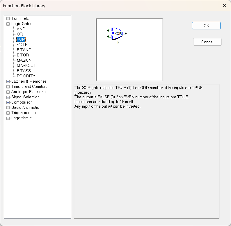
"The XOR gate output is TRUE (1) if an odd number of the
inputs are TRUE (non-zero).
The output is FALSE (0) if an even number of the inputs are TRUE.
Inputs can be added up to 15 in all. Any input or the
output can be inverted."
This looks like the function which will do the job, so click OK
and add the function to the diagram, between the input
terminals and the output terminal.
We only have 2 inputs at the moment, but the explanation tells us
that we can expand inputs up to 15 in all.
For this application we will need 7.
If you left-click within the function block body, you will select the entire function block, including the pins. If you right-click within the function body you will bring up a menu which allows you to:
All the pins on the XOR gate are shown as hollow green squares.
These are
non-inverting digital pins.
Signals arriving at these pins are considered FALSE if they are zero,
TRUE otherwise.
Digital pins can be inverted to make them
inverting digital pins
, shown as red squares with a cross in them.
Signals arriving at thesepins are TRUE if they are zero, FALSE
otherwise.
Inverting pins can be inverted back to make them non-inverting.
Analog(ue) pins are shown as solid blue squares. These pass the value of the signal straight through without modification, and they cannot be changed into any other kind of pin.
Some function blocks are fitted with analogue pins, some with
digital pins, and some with a combination of pin types.
The pin types are matched with the function of the pin -
True/False functions are fitted with digital pins whereas
functions which require or generate a continuous signal are
fitted with analogue pins.
Exceptions to this rule include the terminal functions TERMIN
and TERMOUT, where the same function is used for both digital
and analogue terminals.
These function blocks have analogue pins, which allow for the
passage of both types of signal.
If you want to invert the action of a TERMIN or TERMOUT pin,
you have to invert the signal connected to it.
There are two methods of changing the number of pins on a function block:
Right-click on a digital pin. Choose Invert Pin from
the pop-up menu.
The pin is redrawn in the opposite form.
Repeat the operation, and the pin is restored to its original form.
On our corridor lighting example, we decide that with all 7 switches
off, the lights should be off.
Looking at the XOR gate definition, we see that when the number
of TRUE inputs is even (and 0 is an even number) the output is
FALSE.
So the output signal is in the correct sense for our application.
Right-click on the pin and choose Properties from the pop-up.
This will tell you all about the pin.
After a bit of experience you will be able to see directly from the diagram
what the pin properties are.
When drawing wires, it is important to start and finish in the
right places.
In order to do this, we need tounderstand about Sources
and Destinations.
A signal source is normally the output pin of a function
block, but it can sometimes be an
incoming cross-reference
or a
constant.
A destination is normally the input pin of a function block,
but it can sometimes be an
outgoing cross-reference.
Wires in AmbiLogique diagrams only ever have one source.
Multiple output pins connected together are flagged as an error.
A wire can go to as many destinations as you like - there is no
limit on fan-out.
Wires need to be drawn starting from the source and working towards
the destination.
Select wiring either by clicking the Wiring Button
![]() or by choosing Wire from the Insert menu.
or by choosing Wire from the Insert menu.
The cursor on the diagram will change to a representation of a
spool of wire.
![]()
Locate the start point and left-click. A "rubber band" now links your start point with the moving cursor.
When you locate either the destination or an intermediate point where you want the wire to bend, left-click again. The wire will be drawn in, and the rubber band now stretches from the last point you clicked.
You can now either continue with the wire in the same way,
or if you have completed the wire to its destination,
right-click and the last rubber band will be deleted.
The cursor remains in the wiring mode, so that you can draw in a
new wire in similar fashion.
If you right-click between wire drawing, (that is, when you see
the wiring cursor, but not a rubber band), the cursor reverts to the
normal arrow cursor, and you have finished the wiring operation.
Note that you don't have to wire every bend - if you wire between two points which are on a diagonal, AmbiL_PLC will draw in a wire which runs half the horizontal distance, then runs the full vertical distance, then runs the remaining horizontal distance.
Please note that your wires need to leave an output pin
horizontally, travelling left-to-right, and need to arrive at an
input pin also horizontally left-to-right.
AmbiL_PLC will complain if your wires don't do this.
The connection point on an input pin is half way down the
left hand edge of the pin: the connection point on an output pin
is half way down the right hand edge.
Recent revisions of AmbiL_PLC have connection dots on pins
which help you to start and end wires in the right place.
The procedure above describes how to wire from an output pin to
an input pin. Many signals require you to wire to
multiple destinations, and you have to join wires to do this.
With an existing wire in place, select the wiring tool, and
left-click at some point on the body of a wire segment, or on a
bend.
Wires which cross in a '+' configuration (called a 'X' Junction) do
not connect - so don't try to add a fourth wire to a 'T' junction.
Carry on wiring to the new destination in the usual way.
AmbiL_PLC will sort out the connections when you do the next
wire check.
If you have started the new wire part way along an existing
wire segment, AmbiL_PLC will split the wire segment in two
at the junction point when you carry out the next wire check.
Conversely, if you delete a wire segment from a 'T' junction so that
you have two wire segments in a straight line, AmbiL_PLC will tidy
them up by combining the two segments into a single segment during a
wire check.
AmbiL_PLC will keep wire segments to a minimum automatically.
The name which you give to a signal is stamped on the wire segments
which carry that signal.
The wire name is the same as the signal name.
When you wire to a function block output pin, the wire segment has no name. You can confirm this by right-clicking on the wire segment and selecting 'Properties' from the pop-up menu.
When you run a wire check on the diagram, the wire segment will adopt the name of the function block whose output pin it connects to, if it is unnamed. Then, as part of the wire check, all the wire segments downstream will be stamped with the same signal name.
If you want to give a signal your own name, locate the first segment of the wire (the segment which is connected to the function block output pin), right-click on it and select 'Properties' from the pop-up menu. Type your own name into the Name box in the Properties dialog, then close the dialog with 'OK'.
When you run the next wire check, AmbiL_PLC notes that the segment is already named, so does not rename it from the function block. However AmbiL_PLC does then propagate the name of the first segment to all the segments of the wire attached to it.
Showing the Signal/Wire Name
There are times when you want to show the signal name on
the diagram. For example, when you come to run your
Control Diagram in the PLC, you will be able to examine the values
of signals in the PLC only if their signal names are visible.
From the 'Properties' dialog, click the "Show Signal Name"
check box, and the signal name will be shown just above the centre
point of the wire segment.
Note that signal names are shown automatically on wire segments
which are incoming or outgoing cross-references.
Cross-reference names are placed at the open end of the
wire segment, even if you have ticked the
"Show Signal Names" check box.
You can move wires or groups of wires.
Left-clicking on a wire segment causes it to be redrawn in red,
indicating that it is selected. If you hold down the
Shift or Ctrl key, and left-click on more wire segments, they too
will be selected. Finally hold down the left mouse button
on one of the selected segments and you will be able to drag the
selected items to a new position.
The diagram now looks a mess, because the intermediate positions of
all the items you have dragged is still shown.
Left-click in an empty space on the diagram to redraw it.
You can trim wires, either to make them shorter
or longer.
When you trim a wire to shorten it, make sure that you right-click
on the part of the wire you want to keep.
Then choose 'Trim' from the pop-up menu, and your cursor changes
to a pair of scissors.
The point where the blades meet is the "hot spot"
which will select where the wire segment is to be cut.
Left-click where you want the wire segment to end, and it will be
trimmed to the new point.
This technique can also be used to lengthen wires.
You can delete items from your diagram by selecting them,
then pressing the Delete key on your keyboard.
AmbiL_PLC will ask for confirmation before deleting them.
You might prefer to cut the items to the clipboard
(using Ctrl-X or the Cut button on the toolbar).
This will allow you to restore them if the deletion was a mistake.
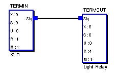
On the toolbar, click on the Wiring Button.
Left-click on the right hand side of the output pin of the XOR
gate.
A rubber-band now runs from the pin to your moving cursor.
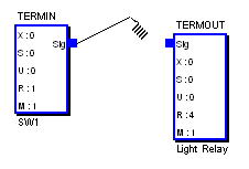
You now need to wire to the input terminal of the TERMOUT function
block, arranging that the last wire segment runs horizontally and
ends on the left-hand edge of the input terminal.
As a first attempt, try your first left-click right on the edge of
the input terminal - if they are not in line, AmbiL_PLC will draw
a 3-segment wire between the two points.
If you miss your target, you can use the
Wiring Adjustments
techniques above to rectify matters.
Again, choose the wiring tool, either from the toolbar, or by
using the Insert->Wire menu sequence.
Start with the output pin of the SW1 TERMIN block, left-click on
the right hand side of the pin, then using left-clicks, wire to
the top input terminal of the XOR gate.
In the same way, wire the other SW input terminals to the remaining
inputs of the XOR gate.
You may need to move the function blocks around to make a
tidy diagram.
Just left-click on a block and drag it.
It will snap to the nearest grid position.
After dragging, left-click in an empty space to redraw the diagram
and see its cleaned-up form.
After moving one or more function blocks, it will be necessary to
adjust the wiring. The wires do not move to follow the function blocks.
When you have finished wiring, look at the status bar at the bottom of the diagram. This should show something like:
| CPDA-02-01 | Sheets 1 | Checked 0 | WCHK ? | COMPILED ? | NUM |
This means that your project is going to use the CPDA-02 processor,
revision 01; there is one diagram sheet, the wiring has not been
checked, and the project has not been compiled.
The next step is to check the wiring.
Select the 'Project->Wire Check this sheet' menu sequence,
or right-click in an empty space on the drawing and choose
"Wire Check" from the pop-up menu.
You should get a "No Wiring Errors" pop-up followed by a
"No Signal Naming Errors" pop-up.
If wiring errors are found, the offending wires are shown dotted.
Use the right-click->Properties technique to find out what
is wrong.
When you have a successful wire check, the status bar at the bottom of the diagram will show:
| CPDA-02-01 | Sheets 1 | Checked 1 | WCHK OK | COMPILED ? | NUM |
Note: We strongly recommend that you save
the diagram sheet immediately after a successful Wire Check.
Right-click in an empty space on the diagram, and select
"Save" from the pop-up menu.
The corridor switching example is a simple one which fits on a
single diagram sheet.
If there were multiple sheets, we would be drawing and checking
each sheet in turn.
When the number of sheets checked is equal to the number of
sheets in the diagram, the diagram is ready for compiling.
Open the 'Project' menu item.
If you have successfully Wire Checked all of the diagram sheets
in your project (one sheet in this example), you will find that
the 'Compile entire project' item, which has been
"grayed out" up till now, is shown in full density.
This can now be selected, and the compilation process proceeds.
If there are errors at this stage, they are normally to do with
cross-references.
The number of errors is shown on a pop-up and the status bar will show:
| CPDA-02-01 | Sheets 1 | Checked 1 | WCHK OK | COMPILE ERR | NUM |
Hopefully the compilation will proceed without problems, and a pop-up indicating success will appear. The status bar shows:
| CPDA-02-01 | Sheets 1 | Checked 1 | WCHK OK | COMPILED OK | NUM |
The compilation process produces two listing (text) files.
The Function Blocks (including "Ghosts" added by the
compiler) are listed in a file called "fblock.lst"
All the wires in the project are listed in a file called
"wires.lst".
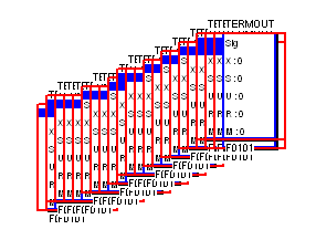
Here is a sample from the "fblock.lst" function block
listing file :-
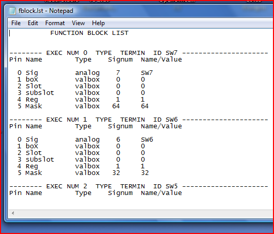
You can see that each function block is listed in order of
execution in the diagram. The AmbiLogique PLC will execute
blocks in the best order for efficient operation of the
control algorithm.
This means that :-
In the listing above, only the input terminals are shown.
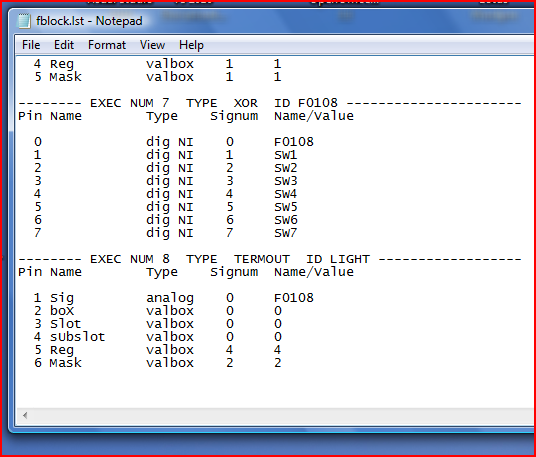
This screenshot shows the last function blocks in the execution
order.
Pin 0 is always the output pin, the others are the inputs from
top down.
Note that the signal fed by the XOR gate, F0108 carries the
same name. This is the AmbiLogique default, but the signal name
could be changed to something meaningful such as “Combined Switch
State.”
The Signum is a reference number assigned automatically by
AmbiL_PLC, and is used internally by the compiler.
Here is a sample from the "wires.lst" wire listing file :-
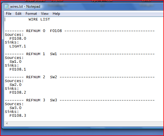
In this diagram there are no constants, so the listing goes straight
into the signals.
See how the wire list relates to the function block listing above.
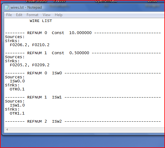
This is a more conventional wire list (for a different project)
which lists the constants first. Note that the reference
numbers for the constants start from 0, and that the refnums
for the signals also start from 0.
AmbiL_PLC knows the difference between constants and signals,
and there is no confusion.
If you get an error message when attempting to compile the diagram,
look at the listing files.
Each error will be flagged with 4 asterisks “****” and a
brief message about the type of error.
Common errors include:-
Click on the Text Button
![]() or choose the Insert->Text menu sequence.
or choose the Insert->Text menu sequence.
The cursor changes to the Text tool.
![]()
Click on the diagram where you want the text item to start.
The Text Edit dialog appears.
This may have the contents of the previous text item, blued out
ready for replacement.
The text content and size may now be adjusted.
Click the "OK" button to complete the text entry.
Note that text items are only single-line.
If you want to insert a block of text, sorry, you have to insert
it a line at a time.
Right-click on the Text item you wish to edit.
The Text Edit dialog appears with the text content blued out
ready for replacement.
If you do not want to replace the entire content, use the left
or right arrow keys to adjust the cursor position,
then insert or delete as required.
The text size can also be changed if desired.
Note that text can be copied or cut to the Windows clipboard
and pasted from that clipboard.
The AmbiLogique clipboard used for cutting, copying and pasting
diagram elements is completely independent of the Windows clipboard,
and using the Windows clipboard in this way will not affect
the AmbiLogique clipboard.
Left-click on the Text item you wish to delete.
Press the 'Del' key and a confirmation dialog appears.
If you click "Yes" the text is permanently deleted.
After selection, you may prefer to cut the text to the clipboard using
Ctrl+X; the deletion can then be reversed.
Click on the Line Button.
![]() The Line Tool appears.
The Line Tool appears.
![]()
This tool operates in exactly the same way as the
Wiring Tool,
except that no connections or other functional changes are made
to the diagram.
Left-click on the line. A red border appears on the line,
showing that it is selected.
The line can be dragged to a new position, either with the mouse,
or by use of the cursor keys.
Pressing the delete key will remove the line from the diagram after
a confirmation dialog.
When the move is complete, left-click in a blank area of the diagram,
and the line will be de-selected.
Right-click on the line. A dialog appears offering the
following options:-
Delete; opens a dialog requesting confirmation.
If you select "Yes" the line is permanently removed.
Trim operates exactly like the Wire Trim tool.
Properties opens a dialog which allows you to change
the start and end co-ordinates, and the line width.
Colour opens the colour select dialog.
We do not recommend black for a line colour - black should be
reserved for wires.
Select toggles the selected status of the line on and off.
There are two clipboards which operate in AmbiL_PLC.
Although they are both operated by the same controls,
one or other will operate depending on the context.
The two clipboards are the Windows and the AmbiLogique.
Copy, Cut and Paste operations in both clipboards respond to
the 'Edit' menu items, the Toolbar buttons, or the
keyboard shortcuts Ctrl+C, Ctrl+X and Ctrl+V.
The Windows clipboard operates whenever there is a text box open
in a 'Properties' dialog.
The Windows clipboard can therefore be used to manage text items, wire
cross-references, or function block names.
This is a very accurate and powerful way to manage cross-references:
without this facility it is very easy to miss hidden characters such
as spaces in signal names, thereby failing to make a connection where
one was intended.
The AmbiLogique clipboard operates at all other times.
Any control diagram items which are selected can be copied
or cut to the AmbiLogique clipboard.
All previous clipboard contents are deleted, so the clipboard
only contains that which has just been copied/cut.
When these items are pasted back, either in the diagram sheet from which they were copied/cut or to a different sheet, the following rules apply:-
When a Paste operation as described above has been carried out,
you will see a partial control diagram outlined in red
(showing that it is selected), but with no Function Block or
Signal names showing.
As soon as the newly pasted material is in the correct position,
carry out a Wire Check. This will cause all of the Function Block
and Signal names to appear.
This all looks a bit complicated (and it is!) but in practice it makes it very easy to move parts of the control diagram to different sheets, or to duplicate parts of the diagram in a way that avoids unwanted connections between the original and the copy, or duplication of refnums (which give rise to multi-source wiring errors).