A Programmable Logic Controller is an electronic device which controls systems or machines based on stimulus inputs and a predetermined set of rules.
It is a box of electronics with means of connecting inputs and outputs, and means of loading and checking the program which determines the rules.
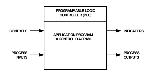
Because PLC's are usually programmed using a graphical language, the program is often called the “control diagram.”
Inputs can either be sensors attached to the process being controlled, or switches, knobs and touch screens on a control panel.
Outputs can either be actuators attached to the process being controlled, or indicators and displays on a control panel.
A Programmable Logic Controller looks at electrical stimuli from
the real world and carries out logical and arithmetic processes on these
stimuli.
Based on these processes, it drives output devices which affect the
operation of systems and/or machines.
The PLC runs continuously unless specifically commanded to stop
(usually for re-programming).
As it runs, it scans all the input devices and generates signals
corresponding to the states of the inputs.
It then works through the control diagram, executing each
function in the diagram until it has resolved everything and has a
set of signals to send to its outputs.
Finally it sets the output states according to those output signals.
Yes, it is. However it is a much simpler device than that PC sitting on your desk or in your backpack.
A PLC is usually devoted to one task, rather than a personal
computer which is expected to do everything.
It also runs continuously, unlike a personal computer which
can be started up and shut down at will.
PLC's are usually designed and manufactured to industrial standards so that they can be relied upon for mission critical applications.
In the early days of industrial control, systems were usually
implemented using relays.
These electromechanical switches continue to have a place in
industrial control, but they are very power-hungry and there
can be a reliability issue when they are used in large numbers.
Another disadvantage is that if the control algorithm is to be
changed, it is out with the toolbox, wire cutters and screwdrivers,
and change the wiring.
This takes time, and the process needs to be shut down whilst this
is happening.
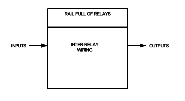
The picture shows a diagram of an industrial process with a box of relays performing the control function.
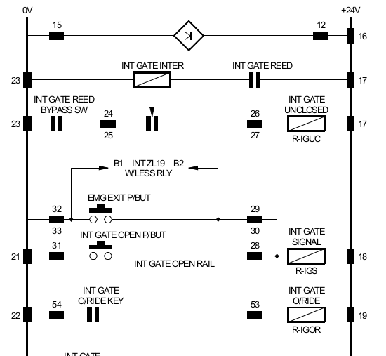
This picture shows a portion of a typical wiring diagram that you might find in one of these systems.
The power feed for the relay coils is shown as two vertical lines, one at the left and one at the right of the diagram.
Each relay coil is actuated when the string of contacts to the left of it allows current to flow through to the coil.
Because the power feeds and the horizontal lines of contacts look like a ladder, this is called a “ladder diagram.”
Some PLC's use this type of diagram for programming.
AmbiLogique uses a different type of diagram (Function Block)
which you can learn about later in the course.
If two contacts, call them A and B are wired in series, then A AND B must be closed for the relay to be activated.
If the two contacts are wired in parallel, then A OR B will activate the relay.
AND and OR are two of the most fundamental operations
in building a control system.
There are loads more, again we'll explain later.
In the late 1960's, the electronics world was revolutionised by the arrival of integrated circuits which implemented the AND and OR functions using very little power, and in a tiny space.
Several companies then started to make industrial controllers based on this new technology, but programming continued to be an issue. Often programs were defined by soldering diodes ito special printed circuit boards - again a painful process if anything needed to be changed.
A few years on, and microprocessors made their appearance. Again, the new technology was pressed into service to make the first PLC's. Programs were written on a separate computer, and blown into EPROMs which could only be erased by subjecting them to intense UV light.
Modern PLC's like the AmbiLogique range use Flash memory built into the microcontrollers, so that programming can be carried out simply by plugging the control computer in, and uploading a control diagram.
All of the above refers to basic logical control in which all of the signals are either ON or OFF. A great deal can be accomplished with this, but it is so much better if continuously variable signals can be input, processed and output.
This is like going from a house where all the lights can be
switched on and off to a house where all the lights have dimmers.
The on-off lights are called 'digital' whilse the dimmable lights
are called 'analogue' or 'analog' depending on which side of
the Atlantic you're on.
Modern PLC's have risen to the analogue challenge, and are
equipped with analogue inputs, outputs and internal functions which
provide a comprehensive range of linear control functions.
You will now find that, in addition to the basic digital functions
and timers, your PLC has a powerful arithmetic unit within it which
can carry out add, subtract, multiply and divide, as well as a
range of trigonometric and logarithmic computations.