When planning a control project, it is a good idea to start with the desired results.
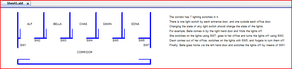
In the first sample project we will look at, we have a corridor
with 5 offices leading off it.
Outside each office door is a light switch.
At each end of the corridor is another door, with a light switch beside it.
This picture was constructed in an AmbiLogique Control Diagram
using just
Decorative Lines and
Text.
This example can be found in your EXAMPLES folder as the Light01 project.
There are 7 light switches in all. When a person
leaves his office, he wants to be able to switch the lights on or off
via the switch beside his office door.
On stepping out of one of the end doors, he wants to be able to
switch the lights off. Conversely, on entering the
corridor at the end, he wants to be able to switch the lights on
if they are off, and may want to switch them off again on entering
his office.
Any of the 7 switches needs to be able to change the state of the
lights.
We can now see that the project has one result: switching the lights on or off.
We can also see that the project has 7 inputs: the 7 switches.
Inputs and outputs connect to the AmbiLogique system via
Terminals.
These terminals are actual screw terminals on the Processor or
Expansion Modules, and they have an exact correspondence with
Terminals on the Control Diagram.
Diagram Terminals are special types of
Function Blocks.
In the same way as there are Input Terminals
and Output Terminals on the AmbiLogique PLC system, there are
Input Terminals
(Function Block type TERMI) and
Output Terminals
(Function Block type TERMO) on the Control Diagrams.
In the example of the corridor lighting system, all of the inputs
and outputs are
'digital',
or 'binary' that is, they only have two possible values:
ON or OFF.
Once we get into the AmbiLogique Control Diagrams, we call these
states TRUE and FALSE, but they can represent any 2-state system such
as STOP-GO, SAFE-UNSAFE, ACTIVE-PASSIVE, LOCKED-UNLOCKED, etc...
If the lights were dimmable, we would need to be able to adjust
the power setting.
In this case we would need to be able to define values between say,
0 and 100% power.
This would involve an output terminal which was capable of a range
of values, called an
analogue
(or analog) terminal.
AmbiLogique input and output function block pins are always
analogue, even when handling digital signals.
There are special rules about handling digital signals in and
out of these analogue pins.
Within the controller, AmbiLogique communicates between the input
terminals, the function blocks and the output terminals by means of
signals.
These signals represent the values generated by the function block
outputs and offered to the function block inputs.
Within the AmbiLogique Control Diagram, signals are carried between the function blocks by means of Wires.
If you have struggled with signal types in other PLC's, trying to
sort out boolean, integer, binary, BCD, floating point and other
types of signals, you will be relieved to know that there is ONLY ONE
TYPE OF SIGNAL within AmbiLogique, and it is called a
"signal."
There are strict rules about what signal values are generated by
binary outputs, and what happens if you connect an analogue signal to
a binary input. We will explain these rules later when
we look at diagrams in more detail.
You will be relieved to learn that these rules are handled by
the AmbiL_PLC software - you only need to understand what will
happen when you make these types of connection.
Within the diagrams, signals travel along wires, starting from a function block output pin and running out to one or more function block input pin. There is no limit to the number of input pins that an output can drive.
It is very important that one and only one output pin is connected
to any wire.
This feature is checked during the per-diagram-sheet
Wiring Check
and during the project-wide
Compile operation.
It is now time to assign the control and sensor connections on the process to the PLC inputs and outputs.
In the case of the CPDA-02 processor in the example, we have wired the switches into the binary inputs (ISW0..6) and assigned one of the outputs (OTR0) to drive the relay which turns the light on or off.
Once we have decided which inputs and outputs do what, we can
carry out the electrical design of the system.
The data sheets for the various modules contain details of
techniques for interfacing to various kinds of sensors and loads.
Assignment of inputs and outputs now enables us to start building
the control diagram.
We can start to add and configure the
output (TERMOUT) and
input (TERMIN)
terminals on the diagram, as explained elsewhere in the help
system (please follow the links for details).
Now that we know which inputs and outputs do what, we can work out
what the properties of each of the TERMIN and TERMOUT function
blocks should be.
These properties are edited into the function blocks once they have
been placed on the diagram.
Right-clicking on a function block will pop up a menu, one item
of which is "Properties.
Selecting this option permits the value boxes in the function block
to be edited, defining which physical
inputs or
outputs
are connected into the diagram via the terminal function block.
Now what remains is to connect the inputs to the outputs via the control mechanisms which give your system its intelligence.